Total Pageviews

Monday 11 April 2016

DEL-YO 1000 concrete lathe plans

Here are first drafts by Ben Bidwell of my Del-Yo concrete lathe. Dave lee is working on another set and has actually managed to draw the mould I have made. It is below.
 amazing hey?!
As soon as I work out how to convert pdf I will post  accurate dimensioned drawings by Ben Bidwell 
Here they are.


Monday 4 April 2016

Yahoo groups mutimachine/concrete lathe prize

I would like to sincerely thank, the yahoo groups forum members who made possible the 4500 SA rand prize awarded to me for the development of the first concrete lathe based on the groups concept. Pat Delaney, you are a genius!
Although my machine does not exactly resemble your outline it is, as we have discussed firmly built upon the very unique engineering principles you outlined.

Monday 28 March 2016

DEL-YO drawings and plans

Ben Bidwell is going to have a crack at putting my Del-Yo lathe into a drawn format. Hopefully with 3D views. He is CAD proficient. I have started updating my sketches with the final sizes taken off the mould. Here are a few more pics and sketches.


Monday 14 March 2016

DEL-YO mould

This weekend saw me completing the cutting and assembling of the concrete mould. Now it's a lot clearer how it will look. Instead of a solid bed, you will note I have made a hollow bed.  This is to save weight as well as to allow space for a heavy concrete saddle, the lead screw and a gap for shavings to fall through. You will see from the photos that I have still not cut any of the core holes for the spindle headstock, leasure and ways. As before, I am adjusting and modifying as I go and want to see how it all looks when together. However. I think my marked holes are going to turn out to be correct. The first two photos show the mould without the headstock and tailstock end enclosures. It's easy to see how the headstock will join to the tail end through the way supports. The hollow way supports are also easy to see. They are quite substantial....250mm by 130mm in section and I think machining resonance will not be a problem with this type of bulk.
Next month,  I will buy the reinforcing rebar and cement and aggregate. I also need to purchase more screws and fasten the mould shuttering more firmly as well as fit the shuttering which is missing on the insides of the leg supports


Wednesday 9 March 2016

Naming the Beast

I am involved with many other interested engineers and mechanics as I build this lathe. I have given a lot of thought to naming this lathe. It's getting awkward just calling it "the concrete lathe". I have therefore decided to name my particular machine a "DEL-YO 1000"
This is am anagram of letters in recognition of "Yeoman" and "Delaney" I believe that the concept deserves due recognition to the innovators who started and put this together. It is also going to be 1000mm bc. Of course, unfortunately many important players such as the draughtsman Tyler Disney, and members of the multi machine yahoo group discussion have played important roles in my final design are not included. But hey!  They are certainly included!

Monday 7 March 2016

The Cross Slide and Saddle

Because of my access to machine tools, where I can, I am fabricating my lathe as accurately as possible. Without doubt, a dovetail section cross slide is definitely going to be more accurate. Therefore I have machined my cross slide with dovetails and will cut a brass gib key for it.

The plate I have used is 20mm x 140mm X 650mm long. I am making a long cross slide because I intend to mount a grinder on the back from time to time as well as use it for milling applications. Progress for me is slow! The materials here in Africa are expensive. This month I bought that steel, some of the other cross slide steel and the chip board for making the shuttering for the concrete main frame. That used an eighth of my disposable monthly salary!

Friday 5 February 2016

Means and ways...

Finding ways is proving to be a challenge. I may use channel and weld rounds onto either end to insert in the concrete way cavities. I'm considering bringing the concrete up and over the channel to assist with the support and resonance suppression. The channels will have to be ground after welding which I can do at work. Here's a sketch of my idea..

Wednesday 3 February 2016

The sketch that started it all...


Concrete_lathe_sketch
Original sketch of 1m BC lathe showing core hole positions for spindle, foot brake etc

Lathe controls

Whenever I have a few spare moments at work I make up bits and pieces for the lathe. Here are a few parts turned for the main carriage control wheel. Materials: 220 mm hydraulic cylinder a old braze tool and a piece of hydraulic shaft. I will mig world them together soon. I have a 200 mm by 600x20mm piece of plate I've had to purchase for part of the cross slide. I want very wide apart ways to support cutting big diameter flywheels.
Carriage cross slide wheel

Tuesday 2 February 2016

Concrete lathe spindle

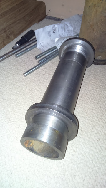
As suggested by Pat Delaney, I have machined the spindle parts out of scrap. The spindle measures 350 mm long and has a through bore of 70mm. It is turned from an old piece of hydraulic cylinder.
Concrete lathe spindle
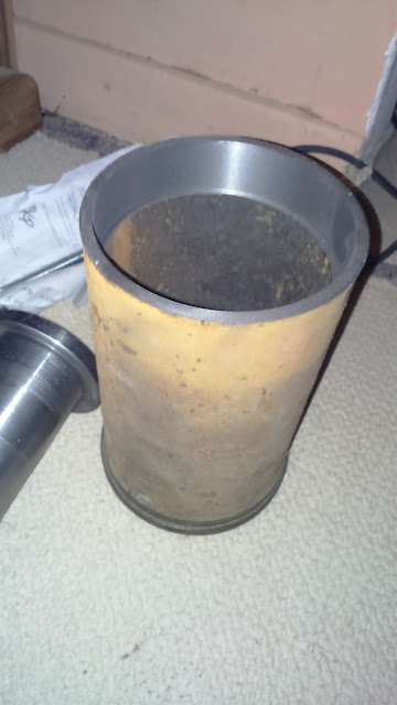
As you can see I have cut a nut and washers. The thread is 76x2mm;a hybrid size!  The spindle bearings housing is an old caterpillar engine wet liner.
Concrete lathe homemade spindle housing using caterpillar wet sleeve
Concrete lathe spindle housing
The bearings are truck taper roller bearings.
You will note I have made everything as big as I can find materials. I intend to build at least a one meter Bc lathe with a swing of about 400mm so I can machine automotive brake drums and clutch flywheels.

Monday 1 February 2016

The lathe bed pattern

This is the next step. Once I have the basic casting done I can begin the more precise setting up of the spindle referenced against the ways.
All credits for the excellent drawings must go I believe to Tyler Disney
The final pattern dimensions. End elevation. I have now roughed out the final dimensions after many changes. To a large extent I have worked from working height of one of our one meter lathes at my work. There are a few notable exceptions. You will notice a massive 400 mm swing over the ways. Accordingly the distance between centres of the ways is also 400. This should give the required stability to the carriage on very big diameter cuts. In any case, the carriage clamp can be employed. I am toying with the idea of making a fitted carriage clamp.
 I would still very much appreciate comments from other engineers on my proposed use of channel tilted to make inverted v ways. Sketch is on my page "ways and means"
here I have marked out the end piece onto some scrap bits of 16mm chipboard(old cupboards) This will be the master. Another 3 will be made off this...obviously the two at the tailstock end will end just above the ways. I intend to place the shuttering for the legs about 130 mm apart to allow for sturdy leg support. I'm still scrounging 8 mm rebar for inserting throughout the casting. 
4 weeks later:
Well I scrapped the idea of using recovered cupboards and pallets and invested in a full sheet of 16mm chipboard to make up the concrete shuttering. I needed accuracy and I needed to mark everything carefully out so that I could visualise the shuttering. I have designed a lathe with a hollow bed. I am trying to avoid simply casting a massive chunk of concrete simply because it's easier! Whilst I want as much rigidity as possible, I also want to keep the Wright under 400 kg if possible so I can move it. Marking out carefully was a splendid idea. Many details of the bed connecting the two ends became clearer. In fact many design details were adjusted as I went along. I used sandpaper to erase pencil markings and re pencilled my lines. Things like the shape of the cavity, where the concrete saddle will fit, the protrusion of things like the saddle, crosslide and tailstock all became much clearer.  I will start boxing the formwork together tomorrow and photograph it as I go. Following are the pics of the cut out end sections. All holes for ways, spindle, controls are still to be finalised and cut. Once again, I will do this "flexibly" as I go!


The beginning...

I have given up trying to build up my machine shop again by buying used equipment. It's all too expensive and out of reach on my salary!
 Because I work as an automotive machinist and fitter Turner, I am going to make my own machinery. My first project is to build a yeoman type concrete lathe.
For those interested in building their own machinery, then watch this blog! Lathe first, then milling machine followed by a surface grinder probably. My aim is to equip myself to carry out light automotive machining One day.
My lathe needs a big swing over bed clearance so I can machine automotive clutch flywheels and brake disks and drums. Here is the link to the inspiration to my idea. Pat Delaneys concrete mutimachine.YEOMANS.pdf
All engineering machines require heavy rigid structures to minimise harmonic resonance. Chatter as it's called by machinists. Concrete is an affordable way of doing this. Concrete is old technology and had been used for making just about anything including ships! Just like conventional metal, it also had shrinkage dynamics that have to be calculated. Pat Delaneys, using early work war technology had illustrated a way to use concrete and "float" the precision elements of the machinery within the concrete. It's logical and it works.

Here are photos of the machined parts I have made so far. They comprise the spindle assembly. Through bore is 70mm. I am doing everything as big as I can afford. These parts are made from scrap hydraulic cylinders and truck taper wheel bearings. The spindle housing is an old caterpillar engine wet sleeve.
Concrete_lathe_spindle_nuts
Close up of spindle machined from old hydraulic cylinder

Concrete_lathe_spindle_housing
Caterpillar engine wet sleeve bored to match truck bearings. This is the spindle bearing housing.

Spindle nuts and washers

Heavy 70mm id Truck bearings used for spindle bearings.